LiPo Stamp
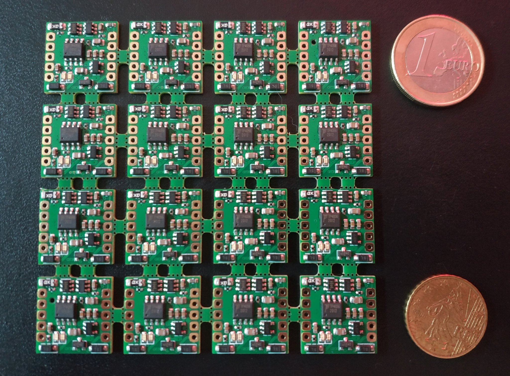
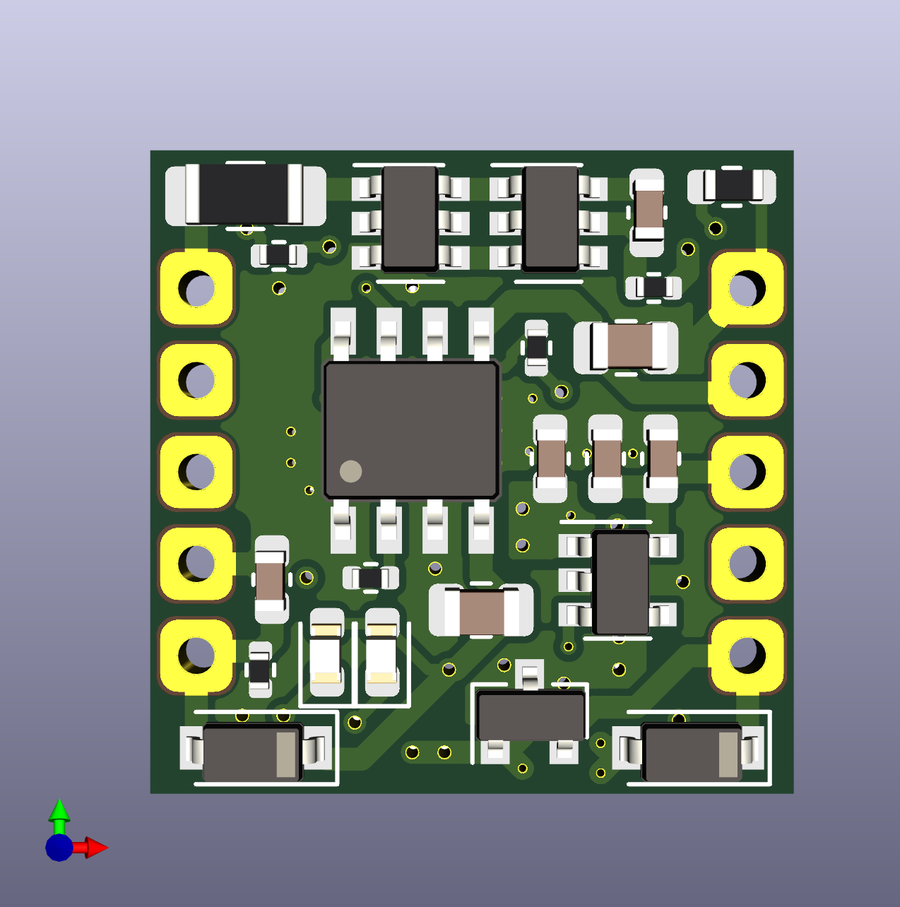
The LiPo Stamp is a small sized, general purpose LiPo charge controller with power path and a 3v3 regulator. Currently the targeted size is 0.7" by 0.7", or just under 18mm square. It is intended to be used with single cell 18650, 21700, pack, or similar batteries.
I intend to use this in projects such as Kuma's Collar.
Features
- TP4056 Charge Controller
- 500mA charging current
- Low voltage trickle charging
- Over/Under-voltage Protection
- AP9101CK6 + FS8205
- Disables battery on over/under charge
- Power Path
- Provides power via USB when connected
- 500mA max output (USB or Battery)
- Switchable 3v3 Regulator
- Default off
- 100mA+ output
- Resettable Polyfuse
- For high current, direct battery applications (e.g. LEDs)
- Max 2A continuous output
The main project page for the LiPo Stamp is hosted on GitHub.
Testing
Implementation of the automated tester is currently going on in this pull request
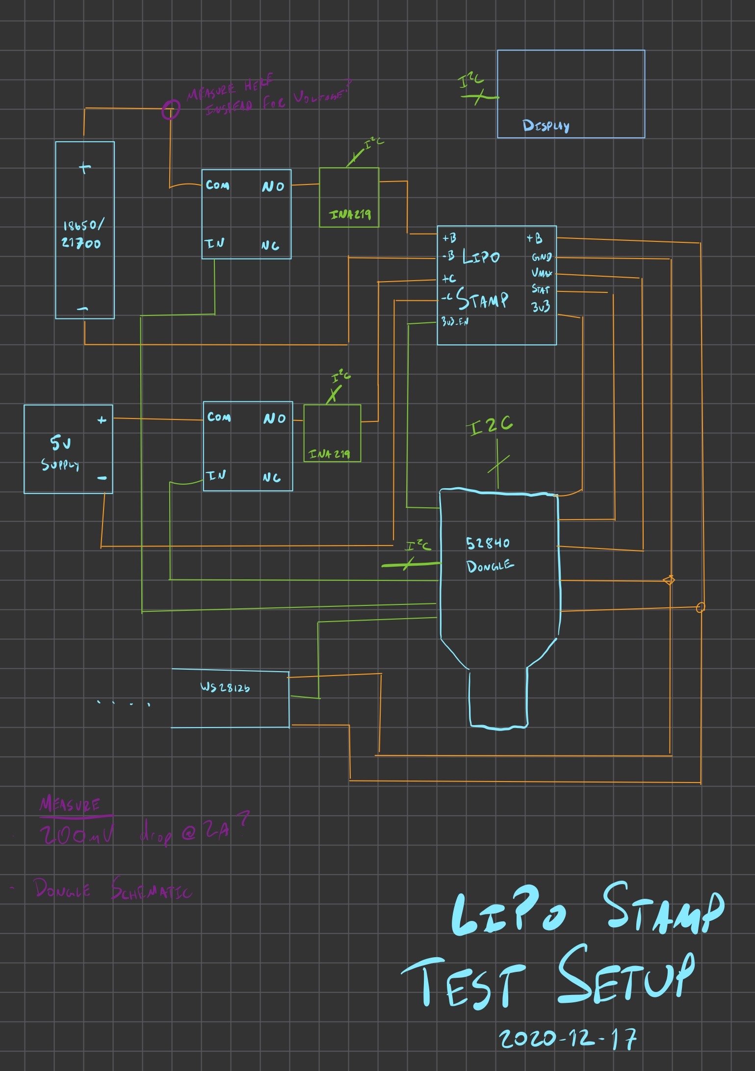
I plan to build a hardware in the loop test rig for the LiPo stamp. It will probably be a proto-version of the KTA, though probably not strictly at the start.
Unsorted test brainstorming
I think I will need the following equipment/setup items for the test cases.
- A LiPo Stamp
- Mounted to a breakout board for easy wiring
- Maybe with headers or screw terminals
- A KTA
- This will "Run" the test
- Also use some ADCs to measure voltage
- Also look control GPIO input/outputs for LiPo stamp
- A 5v supply
- This only needs to provide 500mA for charging, so USB might be suitable if it can power everything
- Otherwise use an external AC/DC supply
- INA219 breakouts
- Measure battery input/output
- Measure 5v charging line
- Relays to connect/disconnect:
- 5v charging source
- Battery connection (high side)
- LED connection (high side)
- WS2812B strip/panel for programmable load
- Some kind of display for monitoring output?
- Protected 18650 cell
- Probably NCR-18650B, rated to 5A discharge, 2.5v cutout
- 3.6v nominal
- PDF Datasheet
- Unprotected 18650/21700 cell
- I might need some kind of custom holder for protected battery cells (if they don't fit the holders I have)
I think I will need at least the following test cases for the board:
- No battery, 5v present
- Check vmax output
- Check 3v3 output (disabled)
- Check 3v3 output (enabled)
- Protected cell
- 5v connected
- Check vmax output
- Check 3v3 output (disabled)
- Check 3v3 output (enabled)
- Verify charging
- Wait for charge complete
- Verify charging complete (no charging)
- Verify LEDs (manual)
- 5v disconnected
- Check vmax output
- Check 3v3 output (disabled)
- Check 3v3 output (enabled)
- Begin discharge pattern
- Verify cutout at low voltage
- Verify LEDs (manual)
- 5v connected
- Polyfuse test
- Charge all the way
- Discharge at steps
- 500mA
- 1000mA
- 1500mA
- 1900mA
- Verify discharge okay, no cutout
- Push discharge above levels
- 2000mA
- 2100mA
- Ensure cutout occurs after XX seconds
- Disconnect load
- Ensure board restores after YY seconds
- Unprotected Cell
- Probably repeat steps above to verify cutout happens because of LiPo Stamp protections, not protected battery
- How to generate load at voltages below the cut-out voltage? We probably need to go as low as 2.5v to verify cut-out.
Test board pinout
- I2C for the INA boards and Display?
- SCL
- PORTB-06
- SDA
- PORTB-07
- SCL
- Analog Inputs
- Battery+ (might be available on INA219?)
- ???
- 5v Source
- Also VBUS for the test system?
- Maybe not? Going through a regulator?
- ???
- Also VBUS for the test system?
- 3v3 Reg Output
- ???
- VMax Output (May be greater than 5v!)
- Voltage Divider?
- ???
- Battery+ (might be available on INA219?)
- Digital Outputs
- 3v3-EN
- ???
- RELAY: 5v Input NO
- ???
- RELAY: Battery Input NO
- ???
- RELAY: WS2812 Panel Connection NO
- ???
- 3v3-EN
- SPI output
- WS2812b Panel
- PORTB-08
- WS2812b Panel